Guide
Logic Gates
How to connect the logic gates
The Logic gates come in a handy box specifically designed to store them without bending the pins on the bottom. It’s important not to bend the pins, as they are for powering the logic gates and transferring power between each set of power rails on the breadboard. To open the box, lift from the tab at the front of the box. (Warning: Have you ever stepped on a Lego Brick? It really hurts. Stepping on logic gates hurts more.)
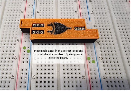
When placing the Logic gates on a breadboard its best to place them with the lower pins on the power rails to maximise the number of logic gates you can add. Make sure you connect them to the top four pins in the left-hand block of 10 pins and the lower 4 pins in the right-hand block of 10 pins, as shown in the image above.
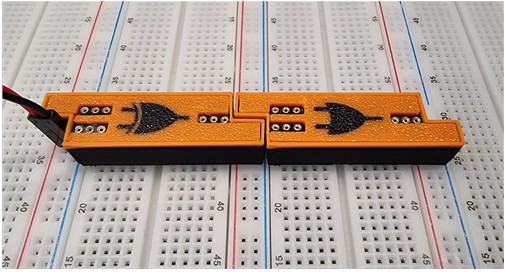
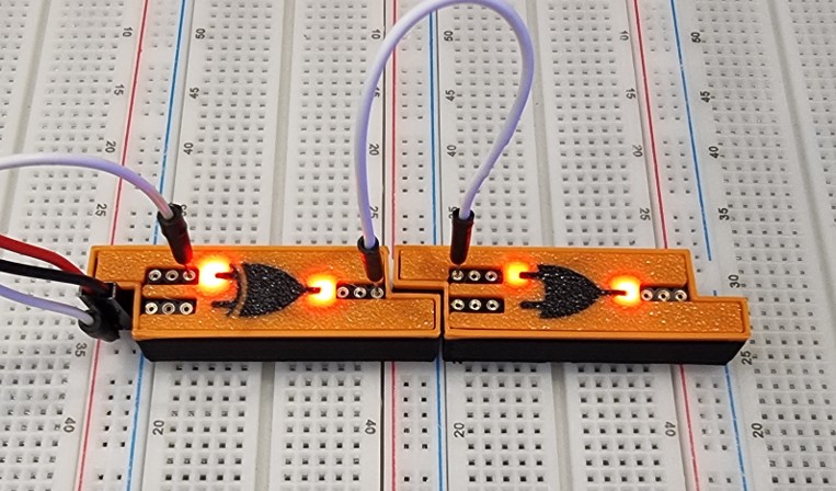
Notice how the first power rail has power connected to it, yet the next set of power rails are now active. Normally, with breadboards, you are required to connect each power rail with power. The BreadboarD GeniuS™ Logic gates, however, carry power between the rails and thus no additional power jumpers are needed. You mustn’t accidentally or incorrectly jumper power wires between power rails or attempt to introduce another voltage level on a power rail connected to a logic gate. The BreadboarD Genius™ logic gates are designed to carry up to 7 amps of power at a maximum of 5V. Do not exceed this voltage. When used within the BreadboarD Genius™ lab, the max delivered power is 4amps, so when used within the BreadboarD GeniuS™ project lab, you won’t exceed this rating. You must connect the logic gates using the GND and +5V connections on the BreadboarD GeniuS™ Power supply unit. If you are using the 0-30V connection, make sure the voltage is set to 5V.
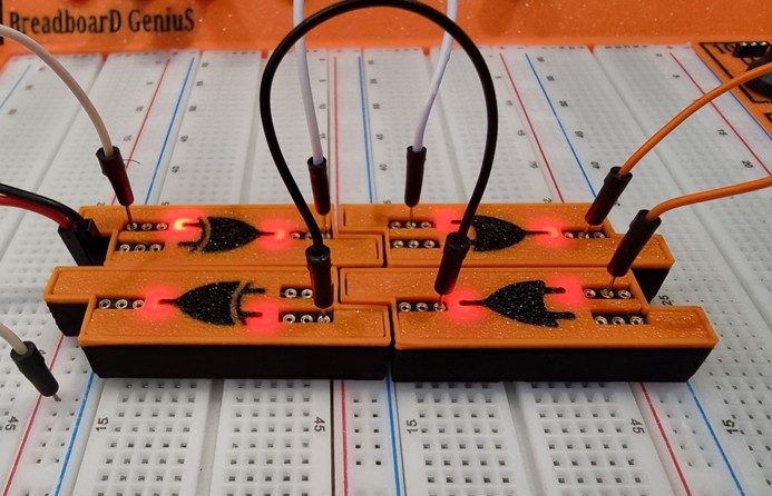
You can plug the BreadboarD GeniuS™ logic gates either way, and both ways on the same power rails. This enables more options when laying out a design and reduces the need for long jumper wires between outputs and inputs.
The input power pins on the bottom can be connected either way; that is, positive/negative can be connected either way around. Within the logic gate is a bridge rectifier to fix any polarity issues. This is why you can plug them in backwards if required.
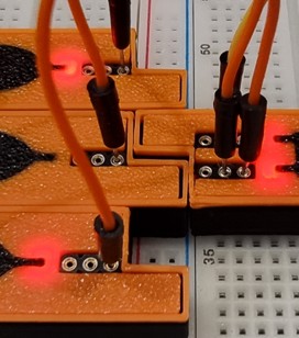
If you connect multiple gate outputs to a single input of another gate, neither gate will activate the opposing gate's output indicator. The BreadboarD GeniuS™ logic gates have been designed specifically this way to show you which gate is active. In a normal logic gate, if multiple gates are connected in this way, then the output of all gates on the same line will become high. If we didn’t add additional circuitry, then all outputs would light up irrespective of the activity of the gate. The negative effect of this is that you can only drive a positive output. When the gate is low, the output is floating; it will not go to ground. Even though it will register at 0 volts, you can’t drive the cathode of an LED as the logic gate won’t sink the current; you can, however, drive an LED to the anode. As the gate's output is isolated using an additional transistor, it can drive a much higher load than a traditional gate. However, the binary/decimal counters' decimal outputs only drive the cathodes, so any devices are sunk to ground when active